Anatoly
Likhnitsky
RX-corrector
(Preamplifier
with RIAA phono correction on the X-transformer)
|
Fig.1. Passive correcting RC-circuit. |
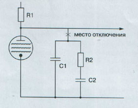
Perform the following experiment.
Disconnect the RC-circuit (see Fig.1) in your pre-amplifier, the one that is
responsible for correction of amplification according to RIAA standard, and
then listen through few of your favorite Lp. For the first few moments it will
sound squeaky and harsh; however, in about 10 minutes you will get used to this
audio disbalance. When you don’t perceive the sound
as annoying any longer, turn on the correction again. You will notice that the
sound becomes “rotten,” “hazy,” slightly “rough,” and coarse. The energy,
dynamic shading, especially in the upper register will disappear, and bass will
become “wadded.” Partially my observations were described in “AM” Vol.3 (4) 95,
p.71.
At first I thought that the increase of high
frequencies and the reduction of low frequencies favors the perception of music
by masking the highs with the lows; however, later I adhered to another
hypothesis: it is the capacitor of the correcting circuit that is responsible
for the deterioration of sound. I tried numerous capacitors of foreign and
domestic brands. Though all of them sounded differently, I noticed the
“signature” of the dielectric in this variety of sounds. This signature is
shown in the Table below:
|
Dielectric |
The type of the
domestic capacitor |
The signature of sound |
|
Milor |
K73 |
Coarse and harsh in upper register |
|
Polycarbonate |
K77 |
Clarity at low frequency,
roughness at high frequency |
|
Polystyrol |
K71 |
Tender, but artificially detailed
high frequency |
|
Polypropylen |
K78 |
Clarity in all range of sound
frequencies, together with the coarseness |
|
Teflon |
K72 |
Brightness in combination with
“viscous” sound |
|
Oil paper |
MBG |
Poor clarity and faintness of
sound |
|
Mica |
SGM |
Clarity of high in combination with
artificial sound of low and middle frequencies |
Besides the dielectric, a capacitor contains
conductors and dozens of meters of aluminum foil. The role of the resistors in
the correcting circuits cannot be neglected. Either way, the main part in this
ensemble is played by the dielectric of the capacitors.
I stopped experimenting with the dielectrics as soon
as I listen the music with the correcting circuits with air capacitors. The last
experiment turned out to be quite difficult. In order to carry it out, I had to
dig out two bundles of AC capacitors from antique German radio sets. The
relatively small capacitance of one section (~ 500 pF)
and its enormous size caused the large background noise at the AC output of the
corrector. Unfortunately, this obstacle is yet to be eliminated completely.
However, the result of “sound” of air-correcting
RC-circuit was far beyond my expectations. It turned out that the air-filled
circuit doesn’t deteriorate the sound. It remains detailed, clear and energetic
as with no RC-circuit. By the way, the effect of “rottenness” disappeared
completely.
I verified it by myself that the main source of evil
in the corrector is due to the dielectric in the capacitors. The results of
this pure experiment were so impressive that I decided to figure out the nature
of the physical processes taking place in the dielectric. I was interested in
understanding why dielectrics are so important for the quality of sound and why
this effect in the capacitors of the correcting circuit is so drastic. Many
times before I have noticed the fact that connecting the capacitors in
different part of the circuit affects the sound considerably less[1].
For now, I have only a hypothesis regarding the
influence of dielectric on quality of sound. I hope that this hypothesis will
sooner or later become a theory and a basis for a doctoral thesis. The idea of
this hypothesis consists of the following.
Unlike the capacitors used to transfer or to block
the power source functions (where the AC component between the plates is kept
close to zero), the capacitors of the correcting RC-circuit (see Fig.1)
function with a continuous change of voltage between the plates. This means
that all the processes in the dielectrics can be observed on the atomic and
molecular levels. They are also observed, but less pronounced in other
circuits. Therefore, these processes turn a capacitor into far from the ideal
element of the sound track.
Among those processes the first to be mentioned is
the dynamic neutralization of the charges on the plates[2].
The neutralization occurs due to dipole orientation parallel to the electric
field lines. By dipoles we refer to polarized atoms, molecules, molecular
conglomerates, etc. Such neutralization has a positive impact on the engineers
since it enhances the optimal capacitance of the capacitors hundreds of times.
However, there is no free lunch.
When AC voltage is being applied, the dipoles in the
dielectric are in continuous rotating motion because of the search for the
right orientation. Their behavior can be compared as of the religious fanatics;
on the one hand, they are unanimous, on the other hand, they interfere
chaotically. This interference, and hence, non-linear and inertial dipole
interaction [1,2] takes place every time the voltage between the plates changes
fast. As a result of such neutralization, a capacitor with a dielectric becomes
a source of frequency-independent inertial non-linear distortions when used in
the correcting circuits.
I have previously been warned by Winer
[3] about the danger of such a distortion for the perception of music. Those
distortions are similar to cancer. Neither a human ear, nor analytical devices
are capable of differentiating these distortions from the musical signal. In
addition, they are not easily detected in a sine wave signal. Therefore, one
can only guess about the presence of inertial non-linear distortions in the
musical signal and its sources.
For example, audiophils
generally believe that the frequency cut at 500 kHz is easily audible. Since
there are no reasonable explanations for this phenomenon, I connected it to the
formation of mid-frequency inertial non-linear distortions in the dielectric
that limit the broadband of the capacitor [4]. By the way, this supposition was
totally confirmed in the course of experiments with the air capacitors.
|
Fig.2. Passive correcting
RL-circuit. |
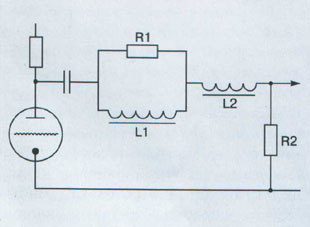
Having lost all hopes to find the non-distorting capacitors
for RIAA correcting circuits, in 1994 I decided to build a pre-amplifier with
the use of RL-correcting circuit (see Fig.2). It was not a pioneering idea.
Already in early 1970-s, the Japanese self-educated engineers have been
publishing the schematics of several RL-correctors. No one has explained yet
why the Japanese preferred the more complicated RL-correctors to RC-correctors.
I will try to fill in the blanks. First, let’s compare the two physical
processes which take place in RC- and RL-correcting circuits.
It’s a known fact that the dipoles in the dielectric
of the capacitor of correcting RC-circuit are in the state of inertial
rotation, which reveals itself in non-linear electric effects.
Magnetic materials, which are used for the induction
cores in RL-correction circuits, have a similar behavior. They are full of
“lazy” magnetic domains that tend to orient themselves along the force lines of
magnetic field. Such orientation results in the magnetization of the core
material. The high magnetization is favorable in this case, because it enhances
the magnetic field created by the inductance. This enhancement can be
characterized by magnetic susceptibility of the core material. It is known that
the magnetic susceptibility, on the one hand, is non-linear for AC current in
the inductor and, on the other hand, is inertial or complex according to
the technical terminology. The theory of complex magnetic susceptibility was
developed as early as in 1913 [5].
It is understandable that the complex, i.e. inertial
magnetic susceptibility of the core material and non-linearity of permeability
are the reason for formation of inertial non-linear distortions in RL-circuit.
Why are RL-correcting circuits preferable to RC-correcting circuits then?
It turned out that the inertial non-linear
distortions in RC-circuits almost do not depend on frequency, whereas in
RL-circuits the distortions fade with the increase of frequency. I’m not going
to provide the proof of this statement due to its complexity.
There is another important circumstance: the use of
RL-circuit gives engineers some freedom in design. They get the possibility to
decrease the inertial non-linear distortions by utilizing the cores of larger
dimensions in the inductances. They can also make the cores from different
materials, say, amorphous iron, or creating air gaps in the inductors, etc.
At the same time, the RL-circuit does not present an
ideal technical solution. The use of RL-circuit doesn’t exclude the creation of
inertial non-linear distortions sensible for ear[3].
In order to prove my suppositions, some tests were
performed on home-made RL-corrector. However, the results of the first
“hearing” showed that my concerns were exaggerated. The corrector was much more
superficial in energy, dynamics, clearness of sound, clarity of high
frequencies and bass articulation than RC-corrector.
Since I was so very much astounded by the quality of
sound of the new corrector, I couldn’t understand why this technical solution
hadn’t been used by the advanced western audio manufactures. Seven years have
passed since, and I do not ask such silly questions any longer. Some of the
predicted sound effects, which I related to the creation of inertial non-linear
distortions in RL-corrector were also observed. They were sensed in a hardly
audible artificiality of the sound. It was then when I decided to continue the
research.
The inspiration came suddenly when I was studying the
pre-war papers written by German engineers from the “Telefunken” company. Why
don’t we try to use the leakage inductance at the output of the windings of the
transformer as elements of the correcting circuit? Really, it was an unexpected
enlightenment. In an instant, everything became obvious, whereas the advantages
of this idea of mine took me long time to comprehend.
My work on the creation of this device lasted for
about two months. Finally, the device was built. Due to the ambiguity of the
used reactances, the device was named RX-corrector.
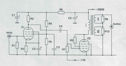
Its schematic is shown in Figure 3.
|
|
|||
|
R1
- 47kOhm R2
- 47kOhm R3
- 1,5kOhm R4
- 47kOhm R5
- 62kOhm R6
- 5,1kOhm |
R7 - 300kOhm R8
- 100Ohm/1Wt R9
- 64kOhm R10
- 5160Ohm C1
- 100μF/350V C2
- 220μF/16V |
C3
- 2,2μF/250V C4
- 0,25μF/300V C5
- 200μF/350V L1
- EF86 (6Ж32П) L2
- EL34 |
|
|
Parameters of RX-corrector
(according to IEC 268-15) |
|||
|
Nominal
EMF source |
5
mV |
||
|
EMF
source at the input overload (1000 Hz) |
130
mV |
||
|
Nominal
output voltage |
0.5
V |
||
|
Output
resistance |
6
kOhm |
||
|
Load
resistance at the output |
>
250 kOhm |
||
|
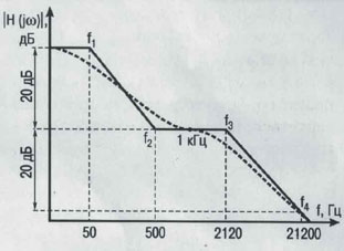
Fig.4. AFC of the
correcting circuit based on RIAA standard. |
My X-transformer became the heart of the new
corrector. Together with the resistive loads, it corrects the AFC
(Amplitude-Frequency Characteristic) according to the RIAA standard (see
Fig.4). This is achieved by the signal addition from the two secondaries of transformers II and III in parallel. Each of
the secondaries forms a certain part of AFC, turning
on one pole. Such poles are produced by the interaction of leakage inductors
and resistive loads at the output of the secondaries.
Those are the resistor R9 for the secondary II and the resistor R10
for the secondary III.
The pole at
the output of III appears at 50 Hz. Above this frequency, the AFC falls with
the slope of 6 dB/oct. At this frequency AFC changes
to plateau-like, developed at the output of the transformer II, which in its
turn changes to the falling part again with the slope of 6 dB/oct at 2120 Hz.
The frequency 500 Hz of “zero” is created when the
transformation coefficient of II is 9 times larger than of III.
Now, when we understand the operational principle
behind RX-corrector, it’s time to find the necessary leakage inductances for
AFC bands.
One can easily obtain the pole at 2120 Hz. Moving a
little ahead, I can notice that it’s sufficient to wind the secondary of II on
the top of the primary of I. It’s much more difficult to form a pole at 50 Hz.
For this purpose, the output inductance at III should be on the order of 20 H.
How to obtain such large leakage inductance? In the
mind-boggling search for the answer, I was urged to solve the problem opposite
to that faced by all electrical engineers of the world. It was required to significantly
increase the leakage inductance. The time has come to “turn your back to the
enemy” as a general gave the order in the movie “Fanfan
the Tulip”.
Using this approach, I have succeeded in creating
X-transformer with the main characteristics listed below:
1.
The required inductance of the primary I needed to obtain
the pre-set threshold frequency of the corrector can be determined as:
![]() H (1)
H (1)
where ![]() is
the internal resistance of the lamp EL34 working as a triode (
is
the internal resistance of the lamp EL34 working as a triode (![]() =
800 Ohm);
=
800 Ohm);
![]() is the optimal load resistance of the
triode, Ohm (
is the optimal load resistance of the
triode, Ohm (![]() Ohm);
Ohm);
![]() is
the pre-set lower threshold frequency of the transformer stage (assume
is
the pre-set lower threshold frequency of the transformer stage (assume ![]() = 1.63 Hz).
= 1.63 Hz).
2.
Transformation coefficients K2 and K3
at the output of the secondaries II and III are
chosen such that RX-corrector provides the amplification equal to 100 at 1000
Hz according to IC 268-15 [6].
Since the signal at 1000 Hz
corresponds to the plateau part of the AFC created by the winding II, the
amplification of the corrector is defined at the output of this winding.
Taking into account[4]
(see Fig.3) that the voltage amplification of the first stage of the corrector
built on lamp EF86 equals 90, and that of the next stage built on EL34 (in a
triode regime with the anode load ![]() )
equals 7.8, one can easily find the transformation coefficients. At the output
of the winding II K2=0.141, and at the output of the winding III K3=0.141x9=1.27.
)
equals 7.8, one can easily find the transformation coefficients. At the output
of the winding II K2=0.141, and at the output of the winding III K3=0.141x9=1.27.
3.
The minimal load resistance for the windings II and III can
be found provided that the total reduced load of X-transformer should be larger
than 2![]() (i.e.
(i.e. ![]() > 1,600 Ohm) and the contribution of
the loads of both secondaries to the load of that
stage should be equal. Then:
> 1,600 Ohm) and the contribution of
the loads of both secondaries to the load of that
stage should be equal. Then:
![]() K22
K22
![]() Ohm;
Ohm;
![]() К32
К32
![]() Ohm;
Ohm;
4.
The values of the leakage inductance at the output of the windings
II and III can be found according to:
![]() (2)
(2)
where ![]() is
the leakage inductance at the output of the secondary, H;
is
the leakage inductance at the output of the secondary, H;
![]() is the RIAA correction pole
frequency;
is the RIAA correction pole
frequency;
![]() is the resistance parallel to the
leakage inductance
is the resistance parallel to the
leakage inductance ![]() .
This resistance includes the reduced to the secondary internal resistance of
EL34, and also the resistance (
.
This resistance includes the reduced to the secondary internal resistance of
EL34, and also the resistance (![]() wind)
of the primary and secondary windings of the transformer, Ohm.
wind)
of the primary and secondary windings of the transformer, Ohm.
For the winding II: ![]() K22
+
K22
+ ![]() +
+![]() .
.
For the winding III: ![]() K32
+
K32
+ ![]() .
.
The resistance of the windings is not known yet;
hence for now we assume that they give a 10% contribution to the total
resistance ![]() .
In this case, in accordance to eq (2):
.
In this case, in accordance to eq (2):
![]() mH
mH
![]() H
H
Now we have reached the ultimate point: determination
of the designing parameters of the X-transformer. The leakage inductance at the
output of the winding II, as has been mentioned above, can be obtained by
winding of the II on the primary. The parameters of I and II can be calculated
by the well-known empirical formula [6]:
![]() (3)
(3)
where ![]() is the average loop length of the
windings I and II, m;
is the average loop length of the
windings I and II, m;
![]() is the number of the loops of the winding II;
is the number of the loops of the winding II;
![]() is the width of the windings, m;
is the width of the windings, m;
![]() is the thickness of the dielectric between the
windings I and II, m;
is the thickness of the dielectric between the
windings I and II, m;
![]() and
and ![]() are the thicknesses of the windings I and II,
m;
are the thicknesses of the windings I and II,
m;
![]() = 0.8 (for non-sequential windings).
= 0.8 (for non-sequential windings).
We see that the formula (3) doesn’t include the
parameters of the magnetic core (the average length of the magnetic field
lines, their crossection and magnetic permeability).
This means that (3) defines an ideal inductance ![]() ,
free from the inertial non-linear effects, caused by the change of the magnetic
cores.
,
free from the inertial non-linear effects, caused by the change of the magnetic
cores.
The next step is to design the part of the
transformer that provides the leakage inductance equal to 21.7 H at the output
of the winding III. It is not possible to solve this problem the traditional
way, i.e. using formula (3) with a reasonable size of the X-transformer. I had
to call for inspiration once again. I tried to visualize how the leakage
inductance is created: when the magnetic flux created by the primary doesn’t
cross the secondary completely [8]; that part of the missed flux has to come
back to the primary anyway, most probably through air. What if one could build
an artificial channel (some flux guide), which would allow the part of the flux
to miss the secondary.
This insignificant, at the first glance, but quite
valuable flash of intuition occurred suddenly. As it always happens, this flash
of intuition pushed me to hard and tedious work. It became necessary to design
an artificial channel for the part of magnetic field in the schematics of the
transformer. It was practically impossible to visualize it, in a long run I had
to use a second breath. In fact, it was necessary to make use of the
dimensionless coupling coefficient K3, which is equal to the ratio
of the magnetic flux through the primary and the secondary to the total flux
created by the primary. This coefficient in its simplest form relates the
inductance of the primary and the leakage inductance of the transformer reduced
to the winding III [8]:
![]() К32 (4)
К32 (4)
Since the values ![]() and
and ![]() are given, we can easily find the value of K3
by reversing this formula:
are given, we can easily find the value of K3
by reversing this formula:
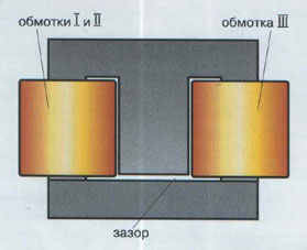
|
Fig.5. Design of the
X-transformer. |
![]() К32
К32
![]()
The value K3 = 0.87 means, from the
physical point of view, that 13% of the magnetic flux created by the primary
(and this is not a small number) should miss the secondary. Having become
positive about the truth of this statement, I moved further towards another
designing solution: to split the magnetic flux right in E-core of the
transformer. In order to achieve this goal, I decided to place the windings I
and III apart from each other, on the side strip of the core, but not on the
center one, as it’s typically done (see Fig.5). In this case, the part of the
magnetic flux of I doesn’t reach III, but is looped back through the center
strip and a specially constructed gap.
The width of this gap can be determined through the
coupling coefficient K3 as a function of the ratio of magnetic
resistances[5] ![]() ,
,
![]() ,
,
![]() of
the different parts of the flux guide in the transformer (see Fig .6):
of
the different parts of the flux guide in the transformer (see Fig .6):
![]() (5)
(5)
Let’s express the resistance of this part of the flux
guide via the magnetic parameters of the core according to the formula [9]:
![]() (6)
(6)
where ![]() is
the average length of the magnetic flux through this part of the flux guide,m;
is
the average length of the magnetic flux through this part of the flux guide,m;
![]() is the the crossection of the flux guide (gap), m;
is the the crossection of the flux guide (gap), m;
![]() is the magnetic permeability of vacuum (
is the magnetic permeability of vacuum (![]() = 1.256x10⁻⁶ H/m);
= 1.256x10⁻⁶ H/m);
![]() is the equivalent magnetic permeability of the
material of the flux guide with DC current in the primary of the X-transformer[6].
is the equivalent magnetic permeability of the
material of the flux guide with DC current in the primary of the X-transformer[6].
Let’s change the ![]() in
(5) to
in
(5) to ![]() ,
,
![]() to
to
![]() and the magnetic resistance
and the magnetic resistance ![]() of the gap to
of the gap to ![]() .
.
Also we will use the typical relations for the E-type
core:
![]() ,
, ![]()
As a result, we will get a simple equation for
calculating the gap:
![]() (7)
(7)
For the X-transformer which has ![]() =0.87,
=0.87,
![]() =450,
=450,
![]() =0.1
m (the typical value in our case), the gap equals to
=0.1
m (the typical value in our case), the gap equals to ![]() m.
m.
Comments
|
Fig.6. The distribution
of the magnetic fluxes and magnetic resistances in E-core of the
X-transformer; red lines define the magnetic fluxes, blue lines show the
magnetic resistances, black lines (in parentheses) show magnetic force lines
corresponding to the magnetic resistances. |
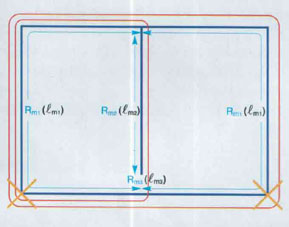
The details in the derivation of the equations (1)
through (7) are skipped, in order to facilitate the explanation.
For example, the two gaps marked with cross in Fig. 6
are not taken into account, though they provide the normal performance of the
flux guide of the X-transformer in the anode current regime of EL34. The interturn capacitors of transformer’s windings are not
taken into account, though they should be accounted for in the process of
fabrication of the transformer. It is important that this capacitance in
combination with the leakage inductance wouldn’t limit the frequency band at
the output of the winding II lower than 20 kHz, and at the output of the
winding III lower than 5 kHz.
Due to mentioned simplifications, the equations for
the leakage inductance can give an uncertainty up to 15%. However, this
uncertainty shouldn’t become an obstacle when setting the poles on the AFC of
the corrector. This can be done exactly
by choosing the values of the resistors ![]() and/or
and/or ![]() .
.
The frequency values of the poles and zeroes on the
AFC of the corrector remain unchanged until the load resistance of the
corrector is larger than 250 kOhm.
The reader should be able to select the size of the
magnetic core, the number of turns and the wire diameter for X-transformer by
him/herself using standard methods [10,11].
The formula of inspiration
The key idea of the RX-corrector is in the
utilization of the leakage inductance as correcting AFC elements. The large
value of the leakage inductance that takes part in the formation of the lower
pole of AFC was obtained by splitting the magnetic flux created by the primary
in two parts, one of which misses the secondary completely.
For this purpose the E-shaped core was used, where
the primary and the secondary windings of the transformer were placed apart
from each other on the opposite side strips of the flux guide. The part of the
magnetic flux created by the primary in this configuration misses the secondary
through the central strip of the E-shaped core and the air gap.
The advantage of RX-correction over RL-correction,
technically speaking, is related to the reduction of the dependence of
inductances on the magnetic parameters of the core.
The leakage inductance at the output of the winding
II that is responsible for the range 500Hz – 20kHz doesn’t depend on the
magnetic parameters of the core, as it can be seen from the equation (3).
Slight dependence on the core magnetic parameters is
exhibited by the leakage inductance at the output of the winding III, which is
responsible for the range below 500 Hz. However, this dependence is much weaker
than the one observed in typical inductors.
In order to prove this statement, let’s compare the
classical formula for the inductance of the winding of III:
![]() (8)
(8)
(where ![]() is the number of turns in III), with the
formula obtained from the equations (4), (5) and (8) for the leakage inductance
at the output of III:
is the number of turns in III), with the
formula obtained from the equations (4), (5) and (8) for the leakage inductance
at the output of III:
![]()
Since 2(![]() +
+![]() )>>
)>>![]() , then
, then
![]() (9)
(9)
The comparison of the equations (8) and (9) yields
the linear relationship between the inductance ![]() and the magnetic permeability of the core
material; in case of the leakage inductance
and the magnetic permeability of the core
material; in case of the leakage inductance ![]() this relationship is
this relationship is ![]() times
weaker. In our case this coefficient equals approximately 27.
times
weaker. In our case this coefficient equals approximately 27.
The magnetic induction[7],
responsible for the leakage inductance on the strips of the core, is about
6.5% from the magnetic inductance in its side strips. Hence, the central strip,
which is responsible for the creation of the leakage inductance![]() works
in lighter duty than the strips used for the signal transformation from the
primary to the secondary.
works
in lighter duty than the strips used for the signal transformation from the
primary to the secondary.
The principle electric circuit of the RX-corrector
|
Fig.7. The picture of my RX-corrector. |
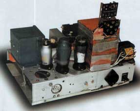
The principle electric circuit of my RX-corrector
slightly deviates[8] from the
one shown in Fig.3. This difference can be explained by the fact that initially
it was designed for controlled AFC correction on 78 rpm. It was made using rare
lamps, magnetic cores and other antique parts that had been manufactured by the
“Telefunken” company in 30-40-ies, and the “magic” chassi,
which I dismantled from the radio “D770.” Mostly owing to all this, my
RX-corrector (see Fig. 7) is very much distinct from any device made by the
contemporary audio manufactures. Most likely, it reminds the handicapped person
of the World War II. However, this cripple by its vigor and substantiation of
sound takes over all contemporary (including the expensive ones) correcting
amplifiers by all means. The invincibility of my RX-corrector I can explain,
first of all, by the application of the described correcting principles. There
is no other mystery in my correction, except for the cited above.
I’m also going to please the readers. Using my
RX-corrector and the technique of the “shortest path of musical signal,” I plan
to record and release two new CDs. They contain old audio recordings, as there
were on my previously recorded CDs. The readers will have an opportunity to
compare the sound of RC-, RL- and RX-correctors.
Using the RC-corrector, I recorded CD “Nikolai Pechkovsky Singing,” “Porgy and Bess” by Gershwin (starring
Louis Armstrong and Ella Fitzgerald), using RL-corrector (1st
version) “AudioMagazin Test CD1,” using RL-corrector
(2nd version with “Telefunken” parts) “Fedor
Shalyapin” and “AML Test CD+” (the picture of the 2nd
version of RL-corrector you can find on the insert to the last CD).
© Likhnitskiy,
2001
(The first publication the author of
this article has taken place in AudioMagazine
№ 5 (40), 2001, pp.167-173 )
Reference
1. Jung W.G., Marsh R.,
Selection capacitors for optimum performance. Part 1&2, Audio, Feb-March
1980, p.52-62 & 50-63.
2. Hippel
A.R. Dielectrics and their application, M-L, 1959, p.336.
3. Likhnitsky A.M., The
relativity formula of sound, “AM” Vol.4 (33), 2000, p.155.
4. Likhnitsky A.M., ibid,
p.151.
5. Arkadiew
W., Phyzik Z., Vol.14, 1913, p.928.
6. Likhnitsky A.M.,
Power. On the correlation parameters of audio components. “AM” Vol.6 (17),
1997, p.96.
7. Tsykin
G.S., Low frequency transformers, Moscow, 1955, p.314 (in Russian).
8. Lendi
Z., Davis D., Albrecht A., The handbook of radioengineer,
M-L, 1961, p.373 (in Russian).
9. Alpatov
N.I., Ferrites in electronic circuits, Moscow, 1962, p.9 (in Russian).
10. Tsykin
G.S., ibid, pp.369-373.
11. Lendi
Z., Davis D., Albrecht A., ibid, pp.384-398.